
St. Elizabeth's West Campus - Central Utility Plant 2
Improving Reliability and Service
HGA partnered with Balfor Beatty Construction to design a new central plant to serve St. Elizabeth’s west campus. The hospital is located on a plateau along the Anacostia hills. The plant, which achieved LEED Gold, offers improved reliability and service as well as significant energy savings—showing a 30% improvement over baseline.
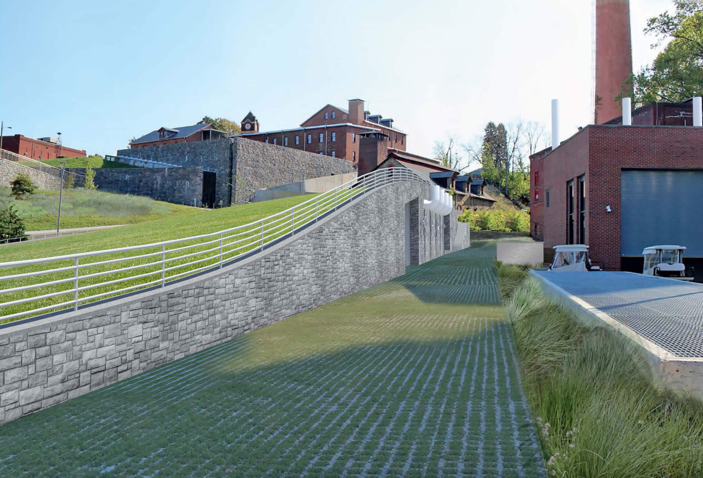
Built three stories underground as an addition to an existing building, the CUP 2 site is both hidden and constrained. This called for major underpinning and site excavation. The design incorporates a clear access path within the space and the structure has removable sections to lower the equipment. All exposed roof surfaces have either intensive or extensive green roofs. All equipment is controlled using HGA’s predictive optimization strategies, programmed into the plant control system. This helps achieve efficiencies rivaling the performance of active optimization.
A portion of the plant is designed for vehicles to drive over it, allowing for emergency access to the existing building, while all exposed roof surfaces have either intensive or extensive green roofs.
The plant is sized for full capacity, however several chillers and one boiler will be installed in the future. This requires a clear access path within the space, as well as removable sections of the structure to lower the equipment. Central Utility equipment includes three 500 BHP heating hot water boilers operating at 200°F. CUP2 is tied to several miles of distribution system with a 24 inch HHW main. Only a few buildings on the loop are currently in operation. There are elevation differences of 170 feet between the lowest point of the system and the highest air handling units in the highest building. Static pressure and pump head for the system required isolating the buildings from the plant with heat exchangers. This isolation improves the resiliency of the plant, isolating the distribution system from individual buildings.
The chilled water system is designed to serve 9,100 tons of cooling in 1300 ton increments. The all-variable speed centrifugal chiller plant includes seven pumps and an ultimate head of nearly 200 feet. Mains leaving the plant are 24 inches and cooling tower mains are 30 inches.
Portfolio