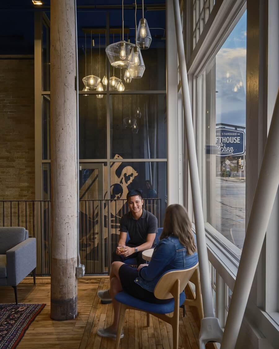
A structural retrofit of Central Standard Craft Distillery’s new home builds on an existing century-old system with modern ingenuity to create an urban destination.
The adaptive reuse of an aging building to create Central Standard Crafthouse & Kitchen, designed by HGA, is as much a structural engineering story as it is an architectural renovation story. For those who have visited the distillery in downtown Milwaukee since its opening in August 2021, you may be curious why the floors slope or the walls and columns lean to the west. The reasons are part of the building’s intriguing history from 1874 up to the present, in which the original construction methods caused the building’s settlement and recent structural repairs transformed a neglected historic building into a vibrant—and safe—local destination.

When Central Standard Craft Distillery, established in 2014, began the search for a larger space, it identified a 16,000 square-foot, three-story commercial building as a new location to add a restaurant, bar, events space, and rooftop patio. To accommodate elements of the new architectural plan like a modern elevator and reconfigured stair at the main entry, I began the process of creating renovation plans to be used by the contractor. Yet, as this work progressed, the deteriorating condition of the long-vacant building would present many new structural challenges.
The severity of the building’s undulating floors and leaning walls shifted the structural focus from more routine tasks like reframing floors to finding a way to assess the condition of the undocumented foundation system buried below the basement slab. This effort began with historical research, which was aided by a recently published article in OnMilwaukee, detailing the building’s history from construction in 1874 through January 2020. HGA’s involvement picks up the story in January 2020 when a test pit was excavated to understand the specific details of the original foundation system. What we found would provide valuable insight into the original construction methods and the likely cause of the slumping walls and floors, as well as guiding the structural repairs that would make the building safe to occupy.
Part 1 – Understanding the deformed shape of building

The building’s current shape results from 148 years of relentless forces pushing and pulling on brick, concrete, stone, and wood. Those forces are related to the weight of the building itself, items stored in the building, occupants, and natural elements like snow and wind. Ideally, the building’s structural system would possess adequate strength and stiffness to resist these loads without failure or permanent deformation. So, what went wrong?
The answer is twofold and includes inadequacies in both the original foundation design and the building’s lateral system (which allows it to resist horizontal forces like wind pressure on the exterior walls). In 1874, the original builders used a foundation system known as timber grillage, where the brick and stone walls were built directly on a grid of timbers – similar in size to railroad ties but placed tightly together and oriented in two layers in alternating directions. The photo on the left shows the timber grillage components in the test pit that was excavated under the basement slab. The level of groundwater was about 12 inches below the top of the slab, so to inspect the timbers, water had to be pumped from the pit.
The presence of groundwater relates to the natural topography in this area at the time of construction. The project site was located at the transition where solid ground, known at the time as the bluff, sloped downward into the marshy area that would later be filled to create Milwaukee’s Historic Third Ward. Though this process created useable space for streets, sidewalks, and buildings, the groundwater is always present beneath. It is likely that the original builder was struggling with the wet conditions at the excavation site with limited options available for a foundation system. State-of-the-art at the time would have been a timber pile system. Timber piles are similar to today’s utility poles. They were turned upside-down and driven into the marshy soils at regular intervals, then topped with horizontal layers of timber and stone. The second option, presumably more cost-effective, was the timber grillage system mentioned previously. We don’t know why the architect and builder chose the system they did, but it may be related to the relatively modest size of the building and the intended life span. The architect and builder almost certainly would not have envisioned the building to still be around in 2022.

Many people are surprised to learn that untreated timbers can be used for foundation systems in wet areas. It seems like they should just rot away but ironically, if the timber sections are fully submerged, air (and more importantly oxygen) is driven from the wood fibers. The oxygen is essential to the organisms that cause decay. In the right conditions, submerged timbers can last for hundreds of years. Our test pit excavation revealed that Central Standard’s foundation timbers were fully submerged and saturated with water, with no signs of decay. So, if the foundation system was intact and functioning as originally designed, what was the problem? The answer relates to the lack of engineering design for the original system. The depth and composition of the marshy soils were simply inadequate to support the building without excessive settlement. We know that because soil borings and geotechnical investigation were performed in 2020 as part of the renovation. The geotechnical engineer stated that consolidation of the organic soils directly under the timber grillage was the likely cause of the settlement.
As to why the brick walls around the perimeter of the building have settled more than the wood-framed interior, it was originally hypothesized that there may have been two different foundation systems. That was later proven to be untrue, as the interior foundations were revealed while excavating for plumbing and structural work beneath the basement slab. The real answer is that the heaviest parts of the building settled the most, and the 12”-thick brick walls comprise the majority of the building’s weight. The interior structure is wood-framed, and its weight is minimal compared to the brick.
In addition to the vertical settlement, the building also exhibits a permanent sag in the westward direction, likely caused by two factors. First, the perimeter walls form a four-sided rectangular brick box, with one notable exception. At the street façade, the ground level is entirely open. One could imagine the conversation in 1874 between architect Edward Townsend Mix and his builder about which was more important … building integrity or windows. It’s clear that the windows won out in this fictitious conversation. True or not, the building has suffered due to the omission of brick or some other structural element in this area. The photo below shows an exaggerated representation of how the front of the building was able to sag to the west. The upper two stories were able to simply translate without distortion, while the lower story leaned.

Second, as shown above, there is additional westward movement of the building that occurs between the front façade and the rear wall. This horizontal displacement was likely initiated by the foundation settlement, but then allowed to continue due to inadequate strength and stiffness of the floor diaphragms. Structural engineers use the term diaphragm when talking about the floors of a building, but in this context, it doesn’t have anything to do with supporting occupants and furniture. Instead, diaphragms function to maintain the shape of the floor plan without distortion and distribute lateral forces to shear-walls and other bracing elements. In the photo (or in person if you look closely), the long straight sides of the original rectangular floor plan have permanently deformed into curved shapes – an indicator of weak diaphragms. In modern wood-framed construction, sheets of plywood are used to create strong and stiff diaphragms. In 1874, they used individual tongue and groove deck boards with hand nailing – yielding weak diaphragms that allowed the deformation to occur.
Part 2 – How do we make the building safe and limit future movement?
Knowing that vertical settlement of the building was caused by poor soils and inadequate foundation design, we presented two options to the building owners. The first was to fully reinforce the entire foundation system using micropiles. (Micropiles are 5” diameter steel reinforced grout columns formed by simultaneously drilling into the mud and injecting a high-pressure concrete mixture to displace the muddy soil. Depths are typically 60’ to 80’.) The second option was to strengthen the existing foundations only at locations where other work was being performed, specifically the new elevator pit, a new shear-wall and new bracing at the front façade. It should be noted that neither of these options included a plan to level the building. Rather, the intent was simply to limit further settlement. After discussion with the building owners, we decided that the first option was cost-prohibitive and didn’t fit within the renovation schedule. Ultimately, the second option was selected, and while it was not as comprehensive as a full foundation retrofit, it was acceptable for the reasons described below.

First, test pits confirmed that the existing foundation system was intact and functioning as originally constructed. Though the original design may have been deficient, any future settlement should at least follow the trend established over the previous 148 years. Similarly, the exposed brick walls show no signs of accelerated settlement or distress in recent years. Unoccupied for many years with no maintenance, a thorough inspection of the brick walls could be performed without having to worry about recent cracks being concealed by paint or mortar repairs. The last factor that influenced our strategy for foundation repairs was intended life span – approximately 20 years of occupancy beyond the completion of renovations in 2021. The structural repairs described in the next section will lessen the potential for further settlement and displacement, but to be safe, we also designed the lateral system to accommodate future movement for 20 more years – at a rate proportionate to the movement that has already occurred.

As mentioned previously, the building’s westward movement occurred because of weak floor diaphragms and the large opening in the south wall at the street façade. The weak diaphragms were reinforced by adding 3/4″ Oriented Strand Board (OSB) or plywood panels. A unique layout and fastening plan was developed for each level based on strength requirements and the condition of the existing subfloor. We chose to apply the new sheathing over the existing subfloor to avoid the mess and disruption of removing it, and also because many of the spaces below have no finished ceilings and the sheathing would otherwise be exposed to view.
An existing stair from a previous renovation created another challenge related to the floor diaphragms (see images below). Specifically, the stair and an existing, non-functional cargo elevator blocked diaphragm access to the north wall. Although the elevator was being fully upgraded to a modern system, it needed to remain in the same location. Similarly, relocating the stair would not be practical. The solution was to introduce a concrete masonry unit (CMU) shaft for the elevator along with a CMU shear-wall located tight against the existing stair. Together, these two elements would anchor the north end of the floor diaphragms. Although simple in concept, the actual construction of these walls would prove to be difficult and consume much of the project’s already-tight schedule. Excavations were required under the basement slab for concrete foundations and as the CMU walls rose out of the basement, carpenters needed to remove the framing at each level in turn so the walls could pass through.

The last piece of the structural puzzle to address was adding lateral strength at the large opening in the south façade. To minimize the visual impact, steel X-bracing was utilized consisting of 2 3/4″ diameter solid round bars. There was initial concern from Milwaukee’s Historic Preservation Commission regarding these visible modifications, but when painted to match the trim color, they are less noticeable. To me, the heavy scale of the exposed bracing, clevises, and turnbuckles provides visual reassurance that the building’s obvious signs of distress have been addressed in a proportionate manner. Steel anchorages were provided at the top of the basement slab, supported by a concrete grade beam spanning the entire width of the building under the front façade.
Amid a flurry of last-minute punch list tasks, Central Standard’s Crafthouse & Kitchen opened on schedule. The structural retrofit was successful, resulting from a careful understanding of the building itself, and the development of historically sensitive repairs that would ensure safe occupancy while meeting the needs of the new owners.
For more information, visit HGA Designs New Home for Central Standard Craft Distillery.
About the Author
Ben Shock, PE, is a Structural Engineer with HGA in Milwaukee.